
Introduction
This tutorial continues from Character LCD Displays – Part 1. In this part we will connect the LCD module to an Atmega8 microcontroller, then write some code to drive it.
The Circuit
Our first task is to build the circuit.
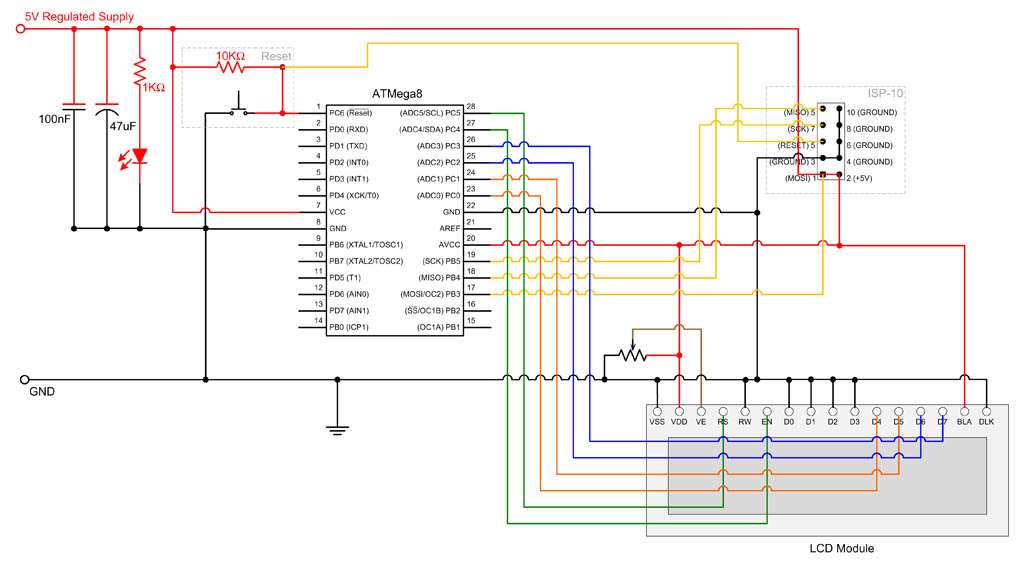
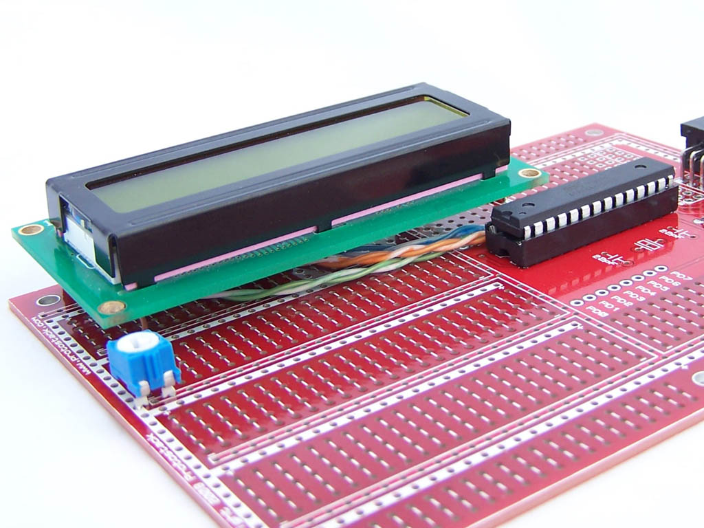
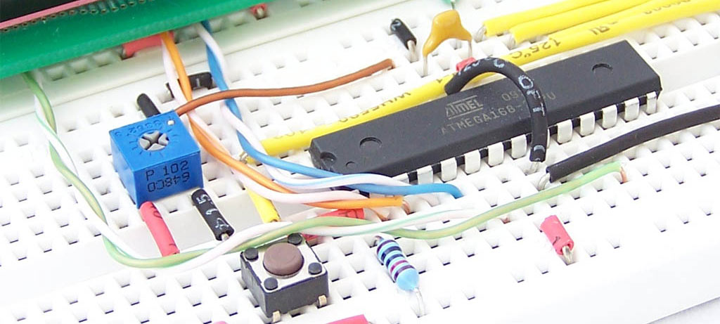
We will be using an AVR 28 pin Development Board. For the power supply we will use a USB to DC Barrel plug cable, so we won’t need to build a 5V regulator circuit. Instead we will run a wire from the barrel connector to the positive power rail, as shown in the photo below.
Also we won’t need an external crystal or AVCC filter block. We still need to run power to AVCC and this is done with a piece of wire.

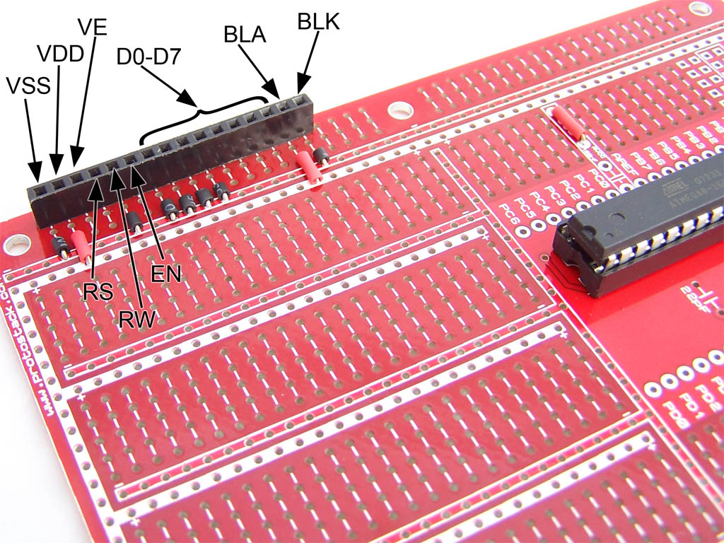
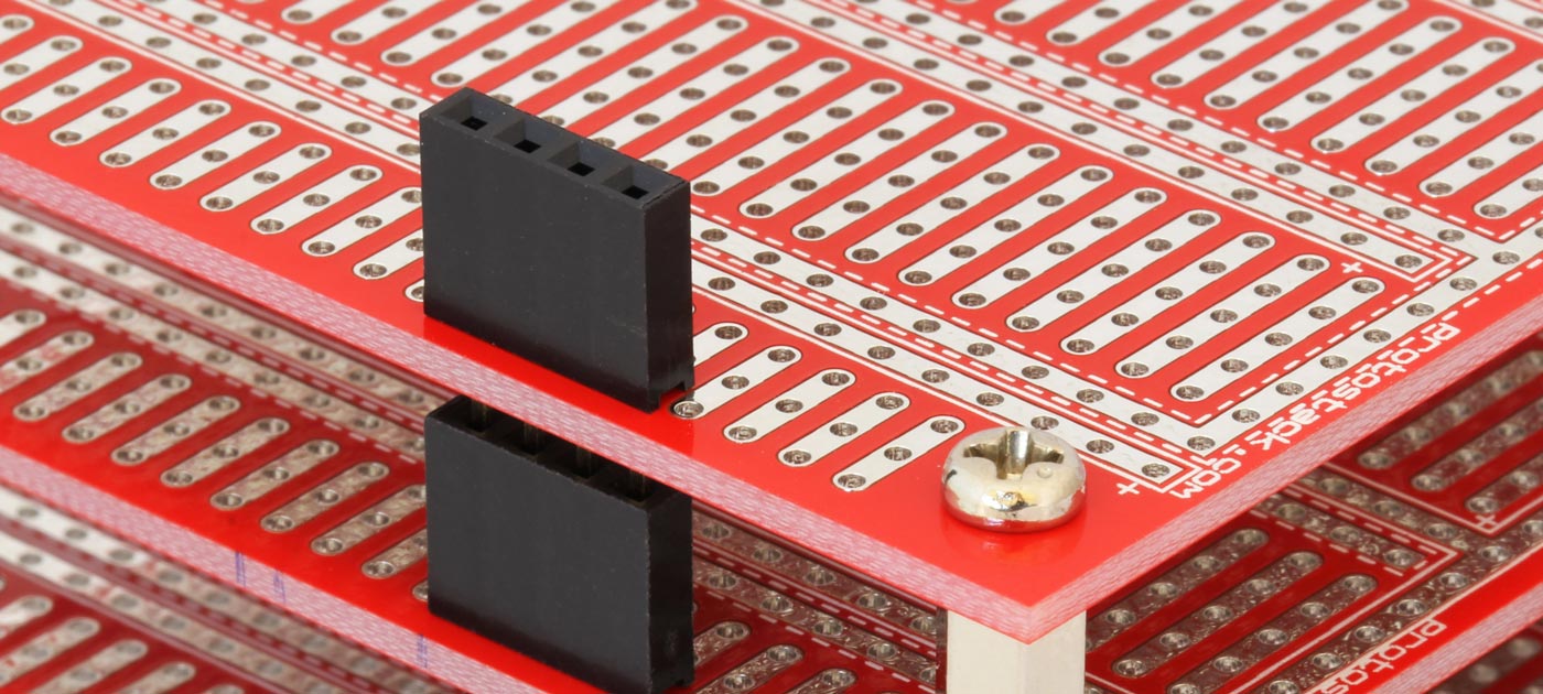
Because we want the ability to remove the LCD module later, we will solder a 16 pin female header to the board.
Next we wire-up VDD and BLA to the positive power rail along with VSS, RW, D0, D1, D2, D3 and BLK to the ground power rail. D0 to D3 are being tied to ground because we will drive the display in 4 bit mode. This lets us drive the display with just 6 I/O lines.
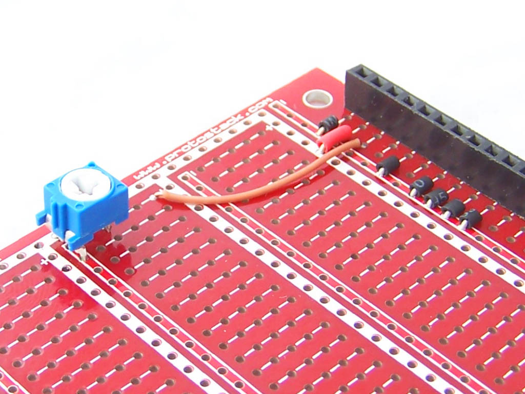
Next we add a trimpot for the LCD contrast. I used a 5K pot, but a range of other values would work as well.
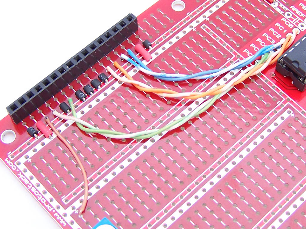
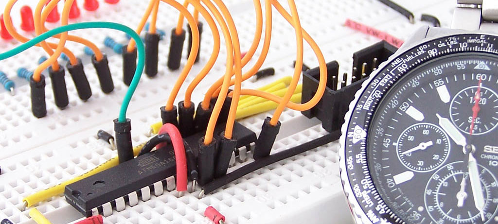
We now connect RS, EN and D4-7 to PC0-PC5. These could have been connected to any of the atmega8 I/O ports, but port C seemed to be ideal as it has 6 usable I/O pins. If you decide to use other pins just change the source code accordingly.
As with the Breadboard example we will solder a 16 pin header to the LCD module.
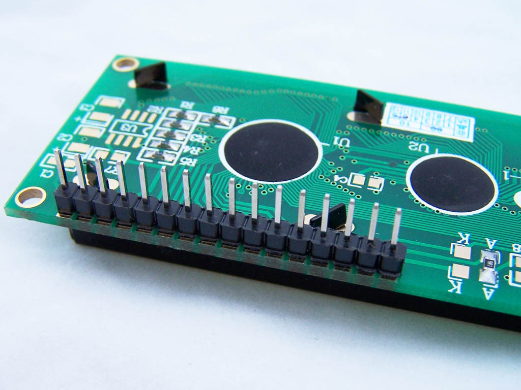
Lastly we attach the module to the female headers.
Coding – Part A
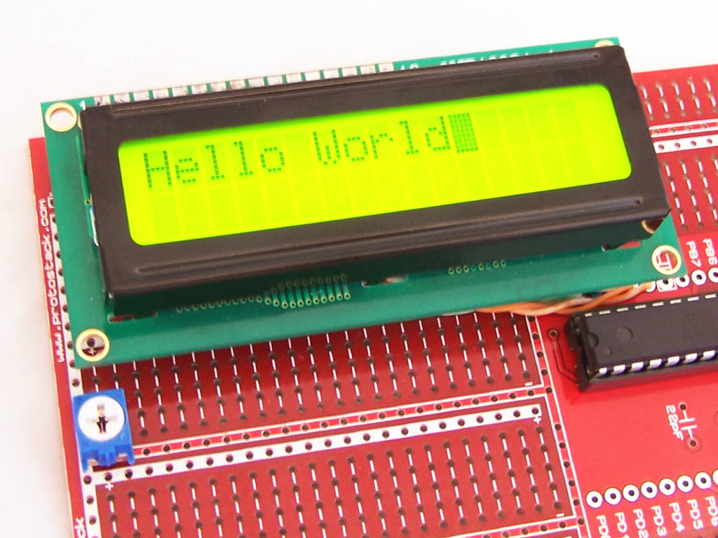
Our first “Hello World” program is below. We are following almost the same series of steps as the 4 bit example in Part 1.
1 2 3 4 5 6 7 8 9 10 11 12 13 14 15 16 17 18 19 20 21 22 23 24 25 26 27 28 29 30 31 32 33 34 35 36 37 38 39 40 41 42 43 44 45 46 47 48 49 50 51 52 53 54 55 56 57 58 59 60 61 62 63 64 65 66 67 68 69 70 71 72 73 74 75 76 77 78 79 80 81 82 83 84 85 86 87 88 89 90 91 | #include <avr/io.h> #include <stdlib.h> #include <util/delay.h> #include <stdio.h> //Define functions //========================================================== void io_init(void); //Initializes IO void send_nibble(unsigned char __rs, unsigned char __data); //========================================================== int main (void) { io_init(); _delay_ms(15); send_nibble(0,0b0010); //Set to 4 bit operation (note: 1 nibble operation) _delay_ms(5); send_nibble(0,0b0010); //Function set, 4 bit send_nibble(0,0b1000); send_nibble(0,0b0000); //Display ON, Cursor On, Cursor Blinking send_nibble(0,0b1111); send_nibble(0,0b0000); //Clear Display send_nibble(0,0b0001); send_nibble(0,0b0000); //Entry Mode, Increment cursor position, No display shift send_nibble(0,0b0110); send_nibble(1,0b0100); //H send_nibble(1,0b1000); send_nibble(1,0b0110); //e send_nibble(1,0b0101); send_nibble(1,0b0110); //l send_nibble(1,0b1100); send_nibble(1,0b0110); //l send_nibble(1,0b1100); send_nibble(1,0b0110); //o send_nibble(1,0b1111); send_nibble(1,0b0010); //Space send_nibble(1,0b0000); send_nibble(1,0b0101); //w send_nibble(1,0b0111); send_nibble(1,0b0110); //o send_nibble(1,0b1111); send_nibble(1,0b0111); //r send_nibble(1,0b0010); send_nibble(1,0b0110); //l send_nibble(1,0b1100); send_nibble(1,0b0110); //d send_nibble(1,0b0100); return(0); } void io_init (void) { /* PC 7: N/A PC 6: Reset PC 5: Enable PC 4: Register Select PC 3: Data 7 PC 2: Data 6 PC 1: Data 5 PC 0: Data 4 */ DDRC = 0b00111111; } void send_nibble(unsigned char __rs, unsigned char __data) { PORTC = (__rs<<4) | __data | 0b00100000; // Set RS & Data. Set EN=High _delay_ms(1); PORTC = (__rs<<4) | __data; // Set RS & Data. Set EN=Low _delay_ms(1); } |
Coding – Part B
The previous example is fine, if all you want to do is understand the principles of how LCD displays are driven, but in practice coding in this manner is a bit painful. To make things easier we need to abstract away the finer implementation details and focus on the operations the developer needs to perform. The easiest way to do this is use a pre-existing library.
A very popular HD44780 AVR library is Peter Fleury’s LCD library. This library is very good but I’m going to use alank2’s slimmed down LCD library instead. My reasons are:
- Peter’s library requires that R/W be connected to one of the I/O ports
- alank2’s library separates out settings into a separate .h file. I think this is a lot cleaner
- alank2’s library compiles a bit more tightly
- alank2’s library supports up to 4 LCD displays, each sharing the same data and RS lines, but having different EN lines.
To use alank2’s library
- Add hd44780.c and hd44780.h to your project
- Create hd44780_settings.h (an example is provided in alank2’s zip file) and tailor it for you project
- Use the provided functions
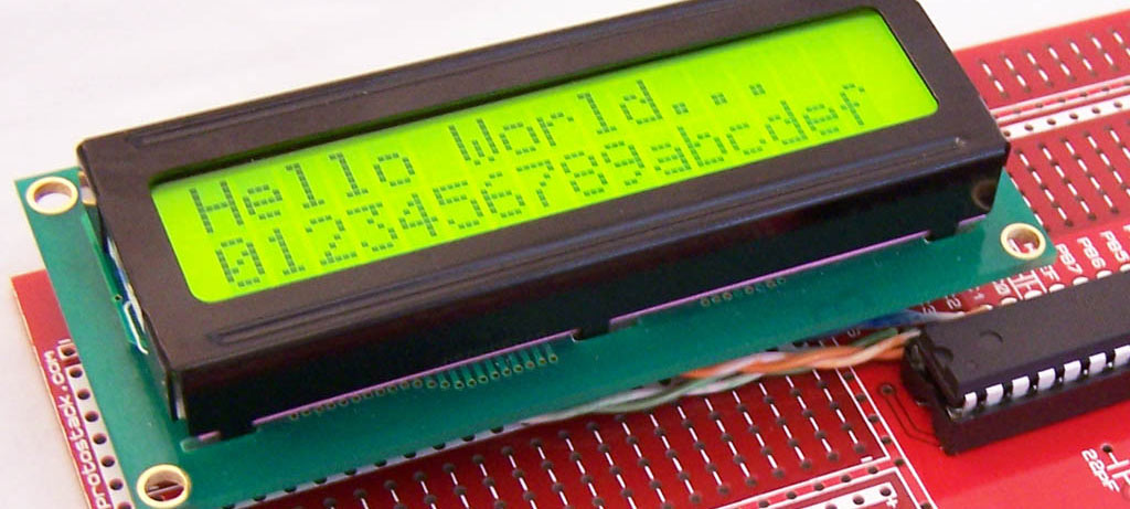
Using alank’s library we create the next example program. This program does much more than our previous “Hello World” example and is only 30 lines of code.
1 2 3 4 5 6 7 8 9 10 11 12 13 14 15 16 17 18 19 20 21 22 23 24 25 26 27 28 29 30 | #include <avr/io.h&> #include <util/delay.h> #include <stdlib.h> #include "hd44780.h" int main (void) { lcd_init(); lcd_clrscr(); lcd_puts("Hello World..."); lcd_goto(40); //Position 40 is the start of line 2 char digit[1]; for (int i=0;i<16;i++) { _delay_ms(250); itoa(i,digit,16); lcd_puts(digit); } _delay_ms(1000); lcd_clrscr(); lcd_puts("Goodbye"); _delay_ms(2000); lcd_clrscr(); return(0); } |
hi
im not getting anything on the lcd screen for part A, except for the screen that comes when you adjust the contrast.help me plz!
thanks
I struggled with this for a long time as well. Switch the RS and EN. The diagram has a slight error on it. Switching these two works perfectly.
how to switch RS and EN
Nice well presented tutorial Thank you for this. I especially love the way you lay out your wiring on that prototyping board.
The code will not compile for part B. Where do I need to save libraries? I complied without making any changes and get numerous warnings and error.
Thank you for this tutorial 😉 The Best of internet LCD tutorials for ATMEL 😉 After switch RS EN working perfect 🙂
HOW TO SWITCH RS AND EN
I can’t quite make out the wiring diagram and when I zoom/enlarge for printing, everything get’s blurred. Without zooming things are just as bad as far making out what you have here. Great article, other than this problem though !!
how a pc lcd can be interface with microcontroller.???
if someone has any idea plz share it