
This is the 3rd part of the workspace project where I describe the cooling system and how it was built.
The desk has an electronics cavity which contains 2 audio filters, 2 stereo amplifiers, 2 power supplies and 2 protostack boards. These all create heat, so a method was needed to ventilate the cavity. The concept was pretty simple, a fan whose speed is dependent on temperature.
Airflow
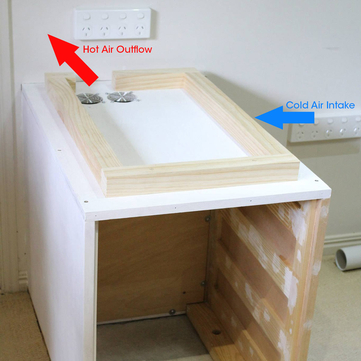

A couple of air outake ports were cut into the top of the pedestal during construction. These vent hot air towards the rear of the desk. An air intake port was cut into the right hand side of the pedestal and a 120mm fan was mounted. The fan selected was a Fractal Design Silent Series R2 120mm.
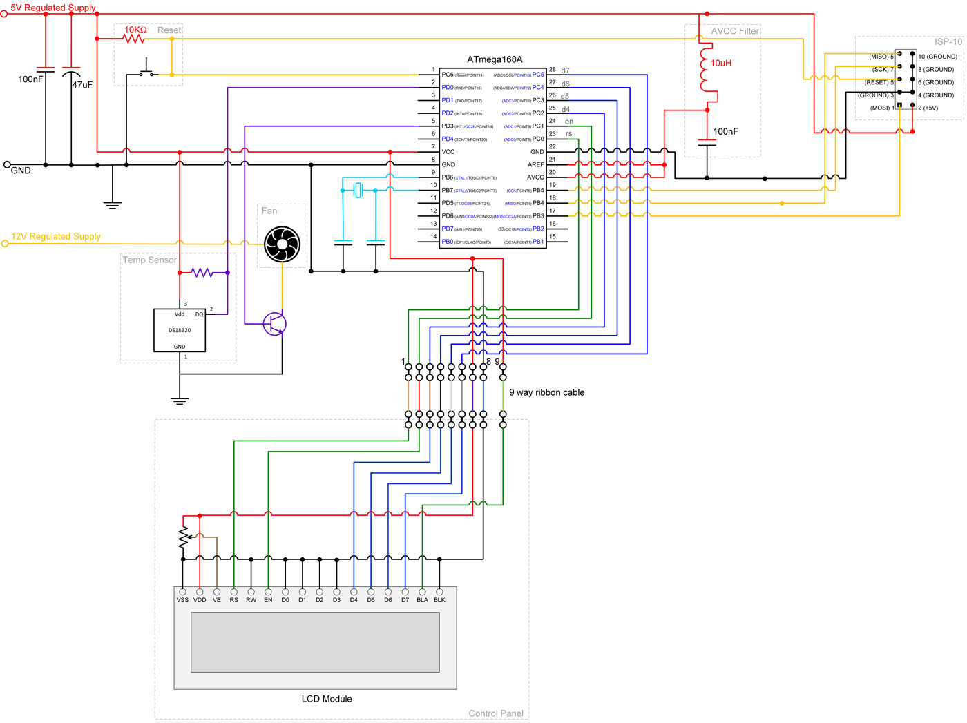
The Circuit
The circuit is based on an atmega168A and built with a 28 Pin AVR Development board.
Controlling the Fan
PC Fans come with either 3 or 4 pin connectors, as shown below
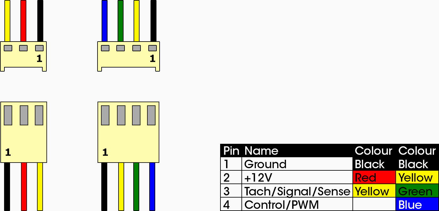
Pins 1 and 2 should be self explanatory, but what do pins 3 and 4 do?
The Tach line (pin 3) is used to report the fan speed to the motherboard. Each time the fan does a revolution, a little blip is made on the tach line. If you count all the blips you can get the fan speed.
The control line (pin 4) is used to turn the fan on and off. This is usually used with pulse width modulation (PWM) to control the fan speed. PWM is simply a technique where you turn something on and off very fast it order to control the speed or brightness of the output. If you are unfamiliar with the concept you can read about it in the ATmega168A Pulse Width Modulation Tutorial.
The fan I was using on had 3 pins, so I couldn’t use the control line for pulse width modulation. I could still control the speed by doing PWM on the 12V line (pin 2). This was driven from PD3 via a TIP31C NPN transistor. The TIP31C was a bit of overkill and I could have used a much smaller transistor if I wanted to.
One thing I did notice is that the pulses required to maintain the fan at a slow speed (about 40% of duty cycle) wern’t enough to start it from an off state. In this case I started the fan at 60% of duty cycle then backed it down to 40%.
Measuring the temperature
Temperature is measured with a DS18B20 Digital Temperature Sensor. I used David Gironi’s DS18B20 1-wire digital thermometer AVR ATmega library to interface to the sensor.
Firmware Source Code
I won’t go into the firmware source code in detail, but it is available using the download link below:
If you have any questions, please use the comments section below.

