In this tutorial I will describe how to drive a 7 segment module using a 4511 – BCD to 7 Segment Latch/Decoder/Driver.
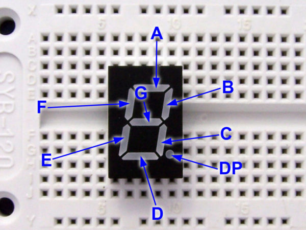
First we need to familiarize ourselves with the 7 segment module. These modules are made up of 8 LEDs, 7 of which make an “8” pattern and 1 for the decimal point. Using the 7 segments, you can make any decimal digit.
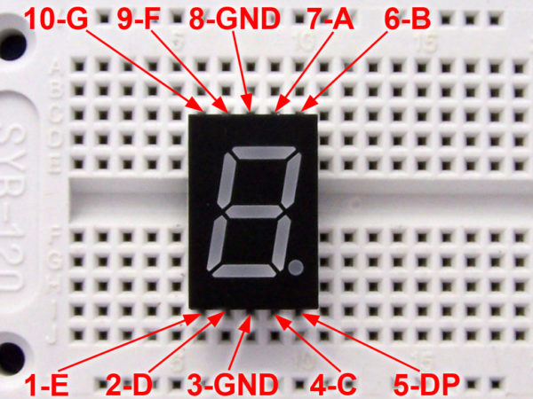
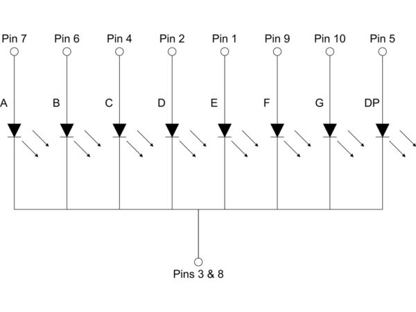
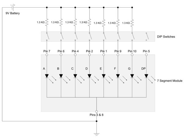
The modules we will be using have a common cathode. This means that the negative side of all the LEDs are connected together. This connection is available on pins 3 and 8.
Each segment is identified by a letter as can be seen below as well as the pinout and schematic for reference.
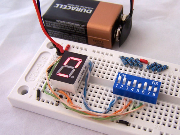
Now we will build a very simple circuit to drive a single digit. We will use a DIP switch to turn various segments on and off. Since this is being powered by a 9V battery, I am using 1.3K resistors for each LED segment. This provides a little over 5ma for each segment. I used the LED resistor calculator on ohmslawcalculator.com to help select the right size here.
With this circuit, you can create any decimal digit you want, plus some things that aren’t valid digits or characters. See the example below.
Now controlling a 7 segment display like this is OK, but we can do much better. With the 4511 – BCD to 7 Segment Latch/Decoder/Driver we can drive the display with just 4 lines. Each 4511 IC takes a binary number as an input, then outputs the necessary lines to display that number on the 7 segment display.
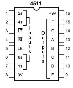
For normal operation, Latch Enable (LE) is held high, but when it is grounded, the 4511 takes the 4 line input and updates its internal registers. The segments are then displayed on the basis of those internal registers.
The pin-out for the 4511 is shown below, and the datasheet is available at here.
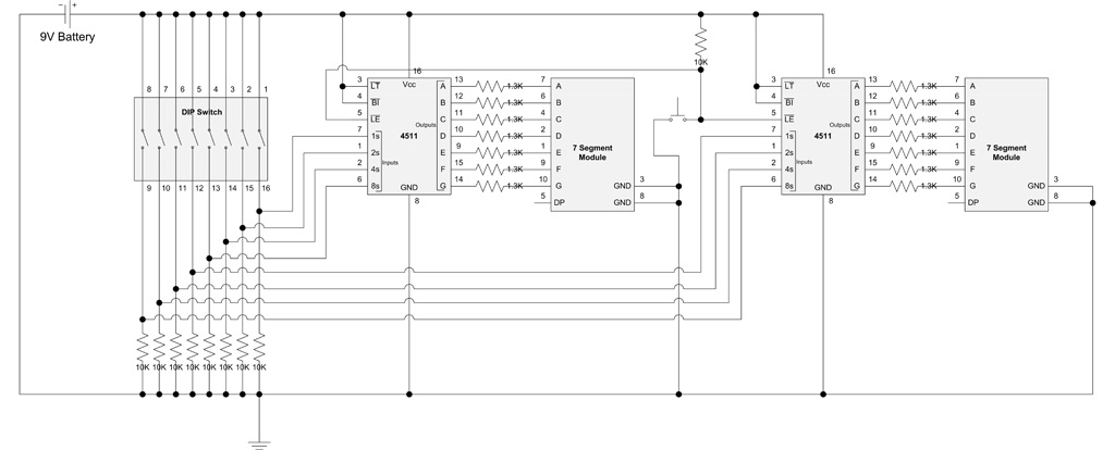
In this example I will be using 2 x 4511 and 2 x7 segment module. The input will be a Binary Coded Decimal (BCD) which means that each decimal digit is individually coded in binary. For example the decimal number “32” is 00010000 in binary and 00110010 in BCD.
Lamp Test (LT) and Blanking Input (BI) are both held high as we don’t want to use these options in this circuit.
The schematic for the circuit is below…
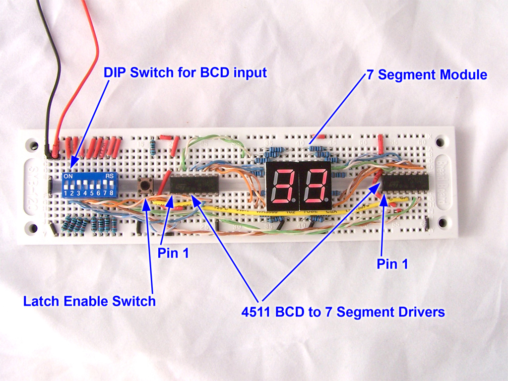
The photo below shows the finished circuit. We are using a DIP switch to set the BCD number, but you could easily substitute a microcontroller or other device.
To use the circuit, simple select your BCD number on the DIP switches, then press the Latch Enable button. Once you do this the number will be updated on the 2 LED modules.




your actual project has diodes in it.
where’s the schematic diagram w/ the diodes on it?
I can’t see the diodes in your schematic ’cause there’s no symbol for the rectifier diodes used there.
1Segment 1 chip red 1.8v
I Have a datesheet
We are factory specialized in making LED 7-segment display, dot-matrix display, light bar display and abnormity digital display.
Thanks and warm regards,
JAY
szdree@gmail.com
http://www.szdree.com
I see no diodes, just breadboard jumpers.
datesheet
The LEDs are the diodes (LED = Light Emitting Diode).
Those are symbol for LED, to represent the 7-segment display, not normal diodes. Hope this explanation helps 🙂
You mentioned drop across LED to calculate resistance, I want to know how much will be the voltage drop across LED is it 0.7V? This is just for information.
thanks and regards,
satya
l like your project…
good!
Im trying to drive a single 7 segment display but i dont know how. i want to spell out someones name on it. can you help me at all??
No.
How much power is used in the 1.3K Resistor and also in the 10K resistor?
Is Latch Enable Switch the same with tactile switch?
i have a piece of electronics with a 7 segment display with a a problem…it’s flickering all “8”s and sorta dim…. possible to share any troubleshooting tips? usually a noisy power related issue or could it be a faulty IC driver?
when the seven Segment is linked with the 4511 through resistors, does it not reduce the intensity of light given by each segment?
yes it does,. Why do you ask?
I ASKED BECAUSE I’M WORKING ON A MINI PROJECT WHICH I WANT THE DISPLAY INTENSITY TO BE VERY GOOD
Every LED has a maximum forward current and forward voltage. If the voltage is too high or the resistor too low (think of the wire being a resistor), the current going through the LED will exceed the maximum forward current and burn out the LED.
What you need to do is select the appriate size resistor which will ensure you still have decent current goiing through the LED without burning it out. This calculator will help you figure out the resistor size http://www.ohmslawcalculator.com/led-resistor-calculator
THANKS VERY MUCH.
THANKS VERY MUCH
IS IT POSSIBLE THAT SOME ONE HELPS ME WITH AN ADRIANO APP THAT I CAN USE TO DO A PROJECT THAT CONTROLS APPLIANCES THROUGH BLUETOOTH? I MEAN A BLUETOOTH APK
IS IT POSSIBLE THAT SOME ONE HELPS ME WITH AN ADRIANO APP THAT I CAN
USE TO DO A PROJECT THAT CONTROLS APPLIANCES THROUGH BLUETOOTH? I MEAN A
BLUETOOTH APp
HELLO CAN YOU HELP ME ON HOW TO TEST IF A TSOP DEVICE IS BAD
HELLO. PLEASE I HAVE A CLASS ASSIGNMENT TO DESIGN A DC/DC BUCK CONVERTER
USING PIC MICRO CONTROLLER BUT DON’T KNOW HOW TO GO ABOUT IT. CAN
SOMEONE HELP PLEASE
EVEN THE DIAGRAM AND THE PROGRAM CODE WILL HELP ME SO MUCH
hi is nice knowing this site, you are doing good work here well done. sir please l want you to help me with a design of a water level sensor to display on a single digit to read out L -low, H-half, F-full with diagrams please thanks
What is the Diode number used here?
can we give 24 V to BCD 4511, If not then kindly tell me its operating voltage (input and output voltage)