Breadboards are invaluable for experimenting with electronic circuits. They allow you to create temporary circuits that can be easy changed. This tutorial explains the basics of how breadboards work and how to use them.
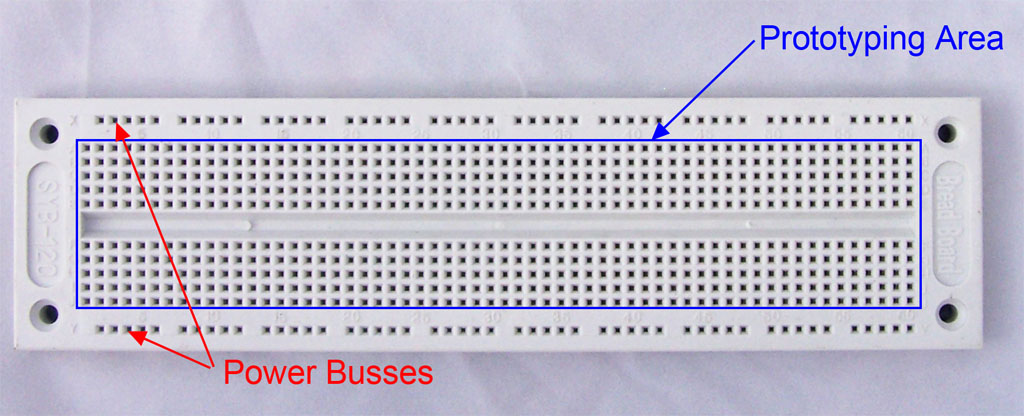
A typical breadboard consists of 100’s of holes called tiepoints. These tiepoints are aligned on a 0.1″ (2.54mm) grid. The board consists of 2 main sections
- Power Busses
- Prototyping area
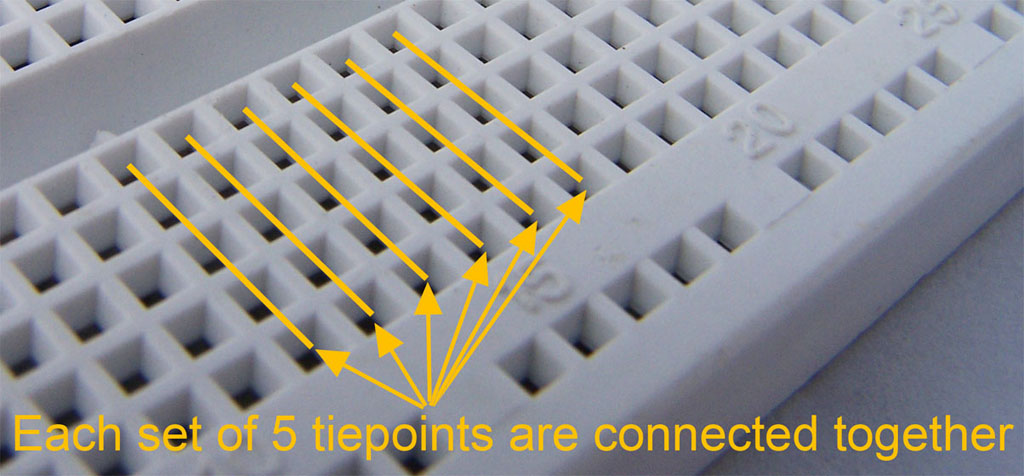
The tiepoints in the prototyping area are typically arranged in groups of 5 which are connected together. These are referred to as terminal strips and are shown in the photo below…
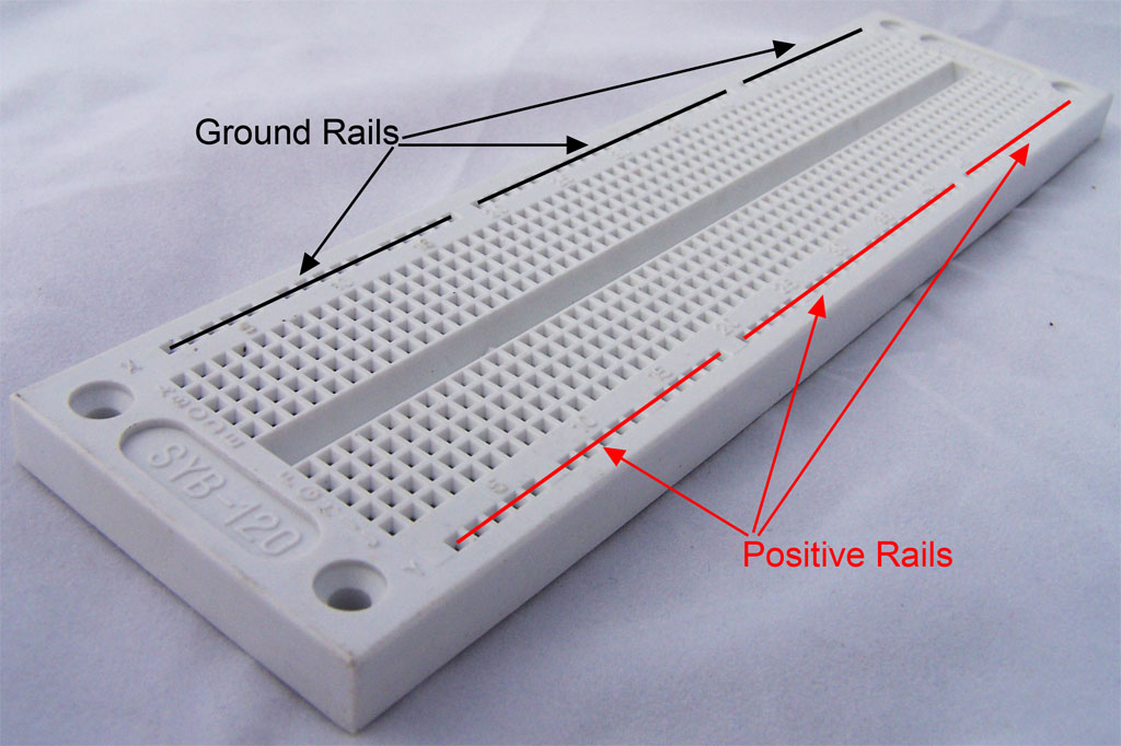
The tiepoints for the power busses are also connected together, but there is usually a break or two in each row of tiepoints. It is common for 1 strip to be used for ground and the other to be used for positive power. These are referred to as bus strips and are shown in the photo below.
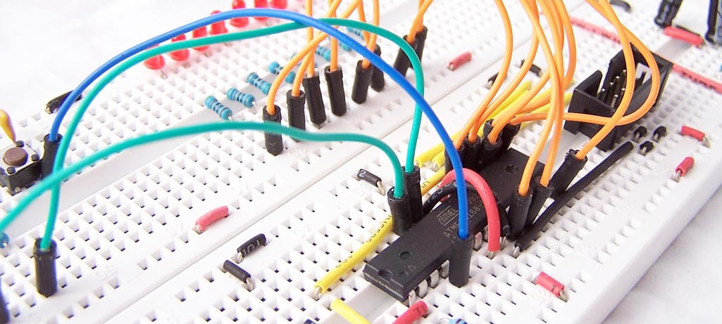
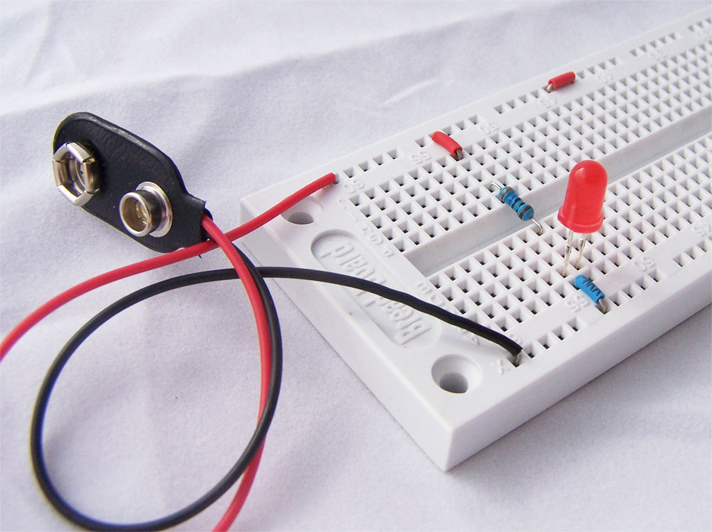
To build a circuit, simply push components or wires into the tiepoints. Components such as integrated circuits in a DIP packages can be placed in the middle of the boards with legs on either side of the conter groove. The photo below shows a simple LED circuit.
can you please translate in filipino.?
use google